Consulting Services, Power Quality Matters
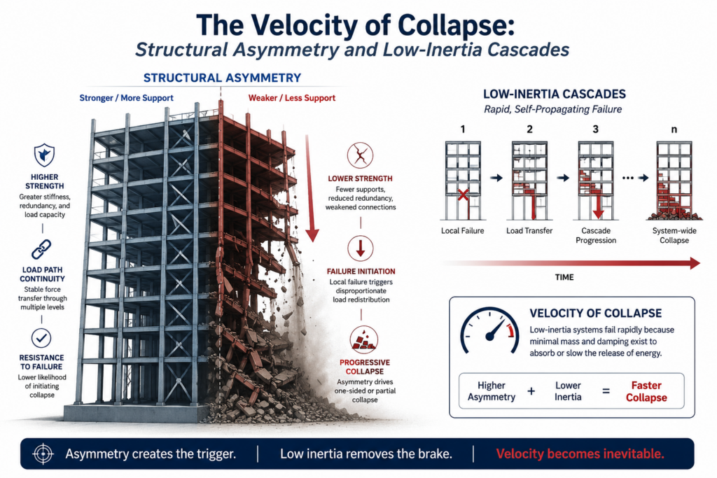
The Velocity of Collapse
Jun
Structural Asymmetry and Low-Inertia Cascades
Modern transmission networks are undergoing a profound structural shift. As massive, synchronous, fossil-fueled generators step down, they are rapidly replaced by inverter-based resources (IBRs) such as wind, solar, and battery energy storage systems (BESS). While this transition pushes the grid toward net-zero targets, it strips the system of its natural electromechanical buffers: System Inertia and System Strength.
In this low-inertia environment, high-frequency anomalies and power quality (PQ) disturbances are no longer localized issues—they act as cascading catalysts for countrywide blackouts. To map this structural vulnerability, we must visualize the high-stakes operational timeline that unfolds when a major network contingency strikes a low-inertia transmission grid.
TIMELINE OF A LOW-INERTIA GRID CONTINGENCY
The Physical Root Cause: Geometric Transmission Asymmetry
While macro-utility managers are hyper-focused on balancing supply and demand, they are entirely blind to the transmission network’s underlying physical geometry. Long Extra-High Voltage (EHV) and Ultra-High Voltage (UHV) transmission lines that remain untransposed behave as silent power-quality contamination factories.
When conductors travel hundreds of kilometers through space suspended over natural terrain, their heights relative to the earth and their spacing relative to one another vary structurally. This structural asymmetry alters the mutual magnetic and electrostatic coupling of the lines, creating highly unbalanced inductive and capacitive reactances across individual phases.
UNTRANSPOSED LINE (Asymmetrical Capacitance/Inductance)
As mapped in the configuration above, without spatial shifting, the physical phase values diverge permanently over long geographical stretches. The un-transposed alignment continually generates Negative Phase Sequence (NPS) components out of pure geometric asymmetry. This unbalance inherently forces electrical equipment down-line to fight continuous counter-torque and severe structural thermal overloads.
The Engineering Remedy: Rigid Transposition Optimization
To structurally counteract this contamination, grid transmission specialists utilize precise line-transposition configurations. By systematically rotating the spatial orientation of the three independent phases at structural interval cycles (specifically broken into balanced geographic thirds), the overall aggregate capacitance and impedance are completely equalized.
TRANSPOSED LINE (Balanced Geometry via Phase Rotation)
When transmission lines are rotated with geometric rigor, the spatial parameters balance out exactly across the duration of the path. This complete cancellation of systemic unbalance drops structural NPS values down close to zero, stabilizing electrical parameters before voltages enter local municipal transformation zones.