Symmetrical Component Analysis
Decoding Unbalanced Systems • Enhancing Fault Diagnosis • Empowering Grid Stability

Decoding Unbalanced Systems • Enhancing Fault Diagnosis • Empowering Grid Stability
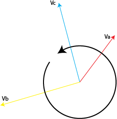
Symmetrical Component Analysis is a powerful engineering technique used to simplify the study of unbalanced three-phase power networks. Based on Fortescue’s Theorem, it breaks down complex, asymmetrical voltages or currents into three independent, perfectly balanced mathematical sets: positive-sequence, negative-sequence, and zero-sequence components.
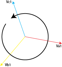
This component represents a completely balanced set of symmetrical phasors rotating in the exact same phase sequence direction (A-B-C) as the original fundamental system. It directly reflects healthy normal operating grid conditions and forms the structural baseline used extensively in steady-state load flow and dynamic network stability analyses.
The negative-sequence component consists of balanced phasors rotating in the inverted, reverse phase direction (A-C-B). This profile arises directly from asymmetrical network faults or heavy unbalances. It induces destructive counter-rotational magnetic forces, driving parasitic heating and severe physical torque pulsations inside rotating motor machinery and line transformers.

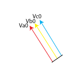
This component consists of three identical vectors that are perfectly equal in magnitude and exhibit zero relative phase shift between them (0° separation). These currents only manifest when a physical neutral grounding path is available, making them crucial indicators for ground fault identification and protective coordination schemes.
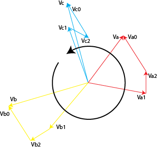
Use the simulators below to see how asymmetrical grid conditions break down. Observe how positive and negative vectors combine to create unbalanced phase vectors.
“Symmetrical Component Analysis transforms complexity into clarity—enabling engineers to diagnose, protect, and optimize power systems.”