
Consulting Services, Power Quality Matters
The Transformer’s Secret Language
Sep
5 Impactful Realities of Modern Power Systems
Decoding electromagnetic signals, hidden fault identities, and the structural vulnerabilities of contemporary power grids.
1. Introduction: The Mystery of the “Ghost” Fault
Imagine the scene: a veteran technician stands in a high-voltage substation, staring with frustration at a primary protection relay. The LCD shows perfectly balanced currents and zero residual ground current. Meanwhile, a few hundred feet away, the secondary-side motor control center is a scene of chaos. A secondary winding is cooking, and the ground-fault alarms are screaming.
To the uninitiated, it looks like a relay failure or a “ghost” in the wiring. But to a seasoned engineer, this is simply the transformer’s secret language. In environments like high-speed rail or heavy industrial plants, what your sensors report is often a “transformed” version of reality. If you don’t know how to translate these electromagnetic signals, you aren’t seeing the system; you’re seeing a phantom.
2. The “Ghost” Fault: Why Ground Faults Change Identity
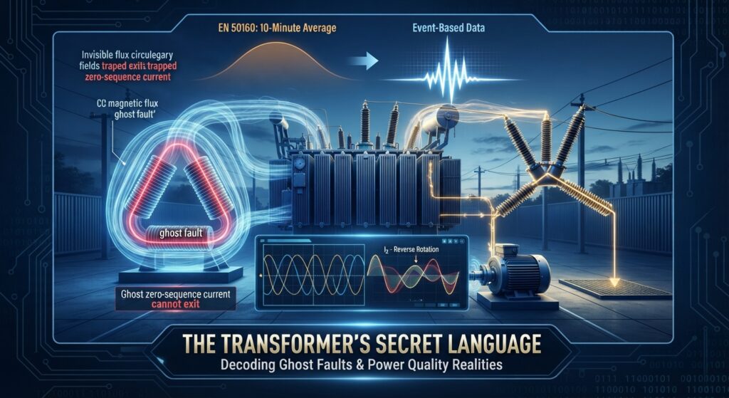
The most common translation error occurs during a single-line-to-ground (SLG) fault on the secondary of a Delta-Wye transformer. On the Wye side, the fault is obvious: current flows through a single phase and returns via the neutral. However, on the Delta primary, the ground current vanishes. It “ghosts,” reappearing instead as a phase-to-phase fault.
This transformation is governed by the principle of ampere-turn balance. As the Industrial Monitor Direct technical reference specifies:
“No winding can have current without corresponding currents in coupled windings. The sum of magnetomotive forces (MMF) must equal zero under fault conditions.”
Because a Delta winding lacks a neutral path to ground, zero-sequence current cannot leave the winding via the line conductors. Instead, the fault MMF triggers an internal circulation—a “ring current” that traps the zero-sequence components within the Delta loop. On the primary lines (A, B, and C), the relay only sees the redistribution of current between two phases. The ground fault has effectively changed its physical identity, leaving primary residual relays (50G/N) completely blind to the catastrophe occurring on the secondary.
3. The Danger of “Reverse” Rotation: Negative Sequence Currents
When a system loses its symmetry—whether through a fault or asymmetric loading—negative sequence components emerge. While positive sequence currents (A-B-C) do the work of turning the motor, negative sequence currents (A-C-B) rotate in the opposite direction of the rotor.
This reverse rotation is physically violent to rotating machinery. It induces “double frequency” currents (100Hz in 50Hz systems; 120Hz in 60Hz systems) into the rotor body. Because of the skin effect, these high-frequency currents do not penetrate deep into the iron; they are forced into a high-resistance path along the rotor surface.
The Mechanism of Damage:
- Surface Concentration: The double-frequency current concentrates in the rotor slot wedges and retaining rings.
- Thermal Runaway: Because these areas are high-resistance, the I2t thermal energy accumulates almost instantly.
- Mechanical Failure: According to Cos Phi data, a 5% unbalance can slash motor power by 25%. More critically, the resulting surface heating can cause rotor wedges to lose mechanical integrity, leading to catastrophic failure within seconds.
4. The 10-Minute Trap: Why Your Power Quality Data Might Be Lying
The EN 50160 standard, the bedrock of power quality compliance, relies on 10-minute fixed aggregation windows. For stable, 20th-century loads, this was sufficient. For modern, intermittent loads like High-Speed Trains (HST), it is a dangerous low-pass filter.
When a train accelerates or brakes, it creates an intense, localized voltage unbalance. If that disturbance lasts for two minutes but is averaged over a ten-minute window, the data is “smoothed.” On your compliance report, the system looks healthy; in reality, the peak unbalance was high enough to stress every motor on the line.
To bridge this gap, we must move toward “Synchronized Aggregation,” grouping data by events rather than the clock.
5. The Clock Position: Why Dyn1 and Dyn11 Aren’t Interchangeable
The “vector group” (Dyn1, Dyn5, Dyn11) isn’t just a nameplate curiosity; it defines the 30° phase shift that dictates which primary phases will carry the burden of a secondary fault. If you are coordinating protection for a secondary phase-a SLG fault, the primary-side mapping changes entirely based on the “clock” position:
- Dyn1 (30° lag): The secondary phase-a fault hits primary phases A and C.
- Dyn11 (30° lead): The secondary phase-a fault hits primary phases A and B.
Actionable Protection Logic: Because the Delta winding “traps” zero-sequence current (the ring current mentioned earlier), residual ground relays (50N/51N) on the primary side are effectively blind to secondary ground faults. This makes the primary phase-overcurrent elements (51P) your last line of defense. For the consultant, this means 51P coordination must be exceptionally tight—if your phase settings are too high, a secondary ground fault could melt the transformer before the primary relay even notices a disturbance.
6. The “Silent Killer” in Induction Motors
There is a dangerous synergy between the “10-Minute Trap” (Section 4) and rotor damage. When the fixed aggregation window hides an unbalance generated by a passing high-speed train, the nearby industrial facility’s induction motors are still physically absorbing that energy. The “ghost” isn’t just a data error; it is a hidden stressor.
A mere 3% voltage unbalance can increase rotor heating by 20%. These small, sustained asymmetries are the “silent killers” of industrial equipment, shortening insulation life long before a total “single-phasing” failure occurs. As noted by Wiringuru:
“Negative sequence protection is a necessary part of any power system protection scheme because even a small percentage of unbalance can lead to overheating, rotor damage, and reduced equipment lifespan.”
For critical motors, relying on standard thermal overloads isn’t enough. Dedicated negative sequence protection (ANSI 46 for current; ANSI 47 for voltage) is mandatory to see the reality that 10-minute averages miss.
7. Conclusion: Beyond the 95% Compliance Statistic
The traditional metric for power quality—95% compliance over a week—was designed for a world that no longer exists. As our grids become populated with high-speed rail, massive power converters, and non-linear loads, our old ways of measuring must evolve.
A system can be “compliant” on a spreadsheet while its assets are being cooked by transient unbalances and hidden fault identities. As we move toward more intermittent and dynamic power systems, the question for every infrastructure lead remains the same: In a world of “ghost” faults and filtered data, is your protection scheme seeing the phantom, or the reality?
