Electric power networks are designed around one foundational assumption: three-phase symmetry. When the electrical parameters of each phase are equal, currents divide evenly, voltages remain stable, and equipment operates efficiently.
But what happens when that symmetry quietly disappears?
One of the most overlooked sources of imbalance in power systems is the untransposed transmission line. These lines may look perfectly ordinary from the ground, yet their geometry can introduce subtle electrical distortions that ripple through the grid – affecting protection systems, equipment lifetimes, and power quality.
This hidden phenomenon rarely receives the attention it deserves. Yet in modern networks – where renewable generation, power electronics, and sensitive loads dominate – the consequences can become significant.
Let’s uncover what is really happening.
The Hidden Problem of Untransposed Transmission Lines
Modern power systems are built around one fundamental engineering assumption: three-phase symmetry. When a power network is balanced, each phase behaves identically – currents divide evenly, voltages remain stable, and equipment operates within its intended design limits.
Yet in many transmission networks this assumption quietly breaks down.
One of the most overlooked sources of imbalance in high-voltage networks is the untransposed transmission line. From a physical perspective the line may appear perfectly normal. Electrically, however, its geometry can introduce subtle asymmetries that propagate throughout the power system.
These asymmetries generate sequence components, distort voltage balance, influence protection systems, and may even shorten the lifespan of rotating machines. In older grids dominated by synchronous generation the effects were often tolerable. In modern networks – filled with inverter-based resources and power electronics – the consequences can become far more significant.
Understanding the role of line transposition is therefore essential for engineers responsible for power system planning, modelling, and operation.
Why Transmission Lines Are Naturally Asymmetrical
A three-phase overhead transmission line consists of three conductors supported on towers or pylons. Because of mechanical and structural constraints, these conductors are rarely positioned symmetrically with respect to one another or to ground.
Consider a typical horizontal configuration:
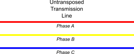
Each phase occupies a unique physical position.
This geometry causes each conductor to experience different electromagnetic conditions:
- Different distances to adjacent phases
- Different distances to ground
- Different coupling to shield wires
- Different electromagnetic fields
These differences create unequal impedance parameters for each phase.
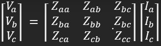
The impedance matrix of a three-phase line can be written as:
For a perfectly symmetrical line:
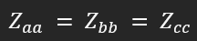
In real overhead lines this symmetry does not naturally occur.
Without corrective measures, each phase develops a slightly different impedance over the length of the line.
The Engineering Solution: Line Transposition
To correct the inherent geometric asymmetry, transmission lines are often transposed.
Transposition means that the conductors periodically swap physical positions along the route so that each phase occupies each position for approximately one-third of the total length.
Typical Three-Section Transposition
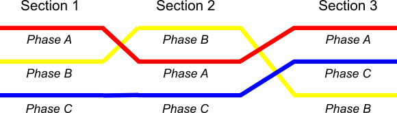
Over the entire line length:
- Phase A occupies positions 1, 2, and 1
- Phase B occupies positions 2, 1, and 3
- Phase C occupies positions 3, 3, and 2
This arrangement ensures that the average impedance experienced by each phase becomes equal.
Mathematically:

after averaging along the total line length.
As a result, the transmission line behaves electrically like a symmetrical system, even though the individual tower geometry is asymmetrical.
What Happens When Lines Are Not Transposed
In many transmission networks – especially older ones – full transposition is not implemented.
Reasons include:
- Reduced construction costs
- Simplified tower design
- Legacy infrastructure
- Shorter line lengths where impact was assumed small
- Mechanical constraints
In such cases, the phase impedances remain unequal:

This asymmetry introduces unbalanced sequence components, even when the load itself is perfectly balanced.
The Physics Behind Transmission Line Transposition
Three-phase overhead transmission lines consist of conductors arranged on towers in a particular geometric configuration. In practice, these conductors are not positioned symmetrically relative to ground or to each other.
Each conductor therefore experiences slightly different electrical parameters, including:
- Self-inductance
- Mutual inductance with adjacent phases
- Capacitance to ground
- Coupling to shield wires and nearby circuits
Because of this geometric asymmetry, each phase develops a different impedance along the line.
To correct this imbalance, utilities traditionally perform transposition – periodically swapping the physical positions of the three phases along the route. The process equalizes the average impedance of each phase over the length of the line and minimizes mutual coupling effects.
In simple terms, every phase spends part of the route in each physical position.
When this is done correctly, the electrical characteristics of the three phases become nearly identical.
The Hidden Consequence: Negative-Sequence and Zero-Sequence Components
In a perfectly balanced system, only positive-sequence currents and voltages exist.
But when phase impedances differ – as occurs in untransposed lines – additional sequence components emerge:
- Negative sequence currents
- Zero sequence currents
These components appear even when the load itself is perfectly balanced.
Studies show that untransposed lines can produce measurable negative-sequence voltages that increase with loading conditions, altering system behaviour and potentially affecting equipment performance.
While the percentages may seem small, their impact can be far-reaching.
Why Sequence Imbalance Matters
1. Additional Heating in Machines
Negative-sequence currents produce counter-rotating magnetic fields in rotating machines.
In generators and large motors this leads to:
- Rotor heating
- Reduced machine lifetime
- Increased thermal stress
These currents behave similarly to fault conditions – even when the system appears normal.
2. Distorted Voltage Profiles
Untransposed lines can create voltage imbalance at the receiving end of a transmission corridor.
Even modest imbalance can affect:
- Industrial motors
- Variable-speed drives
- Sensitive electronic equipment
Voltage unbalance is known to significantly reduce motor efficiency and increase temperature rise.
3. Protection System Challenges
Protection systems often rely on symmetrical component calculations.
However, untransposed lines introduce complex coupling between sequence networks – making traditional modeling assumptions less accurate.
This can affect:
- Fault detection accuracy
- Distance protection calculations
- Fault location algorithms
Modern digital relays can compensate for these effects – but only when the line parameters are correctly modeled.
4. Circulating Ground and Neutral Currents
Geometric imbalance can also create circulating residual currents in grounded systems.
These currents may flow through:
- transformer neutrals
- grounding systems
- shield wires
Such circulating currents contribute to losses and can influence grounding system behaviour.
Why This Matters More in Modern Power Systems
Historically, power systems were dominated by large synchronous machines and relatively stable loads.
Today the situation is very different.
Modern grids increasingly include:
- Solar PV plants
- Inverter-based generation
- Power electronic converters
- Distributed energy resources
- Long transmission corridors
These technologies are more sensitive to network asymmetries than traditional rotating machines.
Even small sequence imbalances can interact with inverter control systems, harmonic behaviour, and voltage stability.
As networks evolve, the assumptions built into classical power system models – such as perfectly transposed lines – become increasingly questionable.
When Should Engineers Worry About Untransposed Lines?
Not every untransposed line creates a serious problem. But engineers should investigate when:
- Transmission corridors are very long
- Lines operate near thermal or stability limits
- Systems include large inverter-based generation
- Persistent negative-sequence currents appear in measurements
- Protection schemes behave unexpectedly
- Voltage imbalance appears without obvious load asymmetry
In many cases, the issue remains hidden because standard power flow tools assume balanced networks.
Only detailed three-phase modeling reveals the true behaviour.
The Engineering Reality: Balance Must Be Measured, Not Assumed
The greatest danger of untransposed transmission lines is not their existence.
It is their invisibility.
These lines rarely trigger alarms. They seldom cause dramatic failures. Instead, they quietly introduce inefficiencies, distort measurements, and complicate protection behaviour.
The modern power grid is already becoming more complex with every inverter, converter, and embedded generator that connects to it.
Ignoring geometric asymmetry in transmission infrastructure simply adds another layer of uncertainty.
For engineers and system planners, the lesson is straightforward:
A balanced power system cannot be assumed. It must be verified.
And sometimes, the imbalance begins with something as simple – and as overlooked – as the physical arrangement of three conductors on a tower.