To proficiently conduct Symmetrical Component Analysis of power systems, one must possess a solid foundation in electrical engineering. Typically, this requires earning a master’s degree in electrical engineering, wherein specialized courses in power system analysis and symmetrical components constitute the core of the curriculum. Alternatively, an individual with an in-depth understanding of Power System Analysis and a fervent dedication to mastering this concept can also achieve proficiency through focused study and practical application.
While the concept of power quality might seem abstract, it is a fundamental pillar for commercial and industrial facility managers. Ensuring good power quality enhances operational efficiency and safeguards employee safety. Furthermore, good power quality can significantly boost productivity and prevent expensive equipment damage. On the other hand, poor power quality can result in substantial financial losses due to diminished productivity and product spoilage.
On a global scale, power quality issues have profound economic repercussions. For instance, poor power quality costs the European economy up to €150 billion annually, while the U.S. incurs losses ranging from $119 billion to $188 billion. Astonishingly, 80 percent of power-quality disturbances originate within the facilities themselves.
In South Africa, addressing power quality is of paramount importance, especially in light of challenges such as aging infrastructure and load fluctuations. Raising awareness, demanding accountability, and advocating for higher-quality power are essential measures to ensure business success and sustainability in the region.
Unbalanced Networks Conditions
While I had the option to replicate the full explanation of Symmetrical Component Analysis from the Agulhascorp website into this text, I chose a different approach.
To understand the rationale behind this analysis and gain insights into Negative Phase Sequencing, I encourage you to explore these topics further. This will equip you with the necessary background to comprehend the forthcoming discussion.
Detecting Power Network Imbalances
The inquiry often arises: Are power network imbalances localized to specific regions? Is their presence easily discernible? Can anyone identify such incidents? In this study, I delve into the complexities of detecting power network imbalances. Without the appropriate instrumentation and analytical expertise, pinpointing these imbalances remains elusive. For instance, merely measuring phase-to-phase and phase-to-neutral voltages falls short of revealing the full extent and severity of power network imbalances.
To address this, I present two real-life scenarios that illustrate this phenomenon. Accompanying online videos on our website enhance comprehension, allowing viewers to grasp the underlying concepts more effectively.
Causes of Voltage Unbalance
Voltage unbalance occurs when the magnitudes of the three-phase voltages in an electrical system are unequal. Some of the reasons behind this phenomenon are:
- Variation in Line Characteristics: Differences in properties, such as resistance or impedance, among the electrical lines used for transmitting and distributing electricity can lead to voltage unbalance.
- Uneven Distribution of Electrical Loads: If one phase carries a heavier load than the others, it results in unbalanced voltages. Unequal power drawn from electrical devices can cause this imbalance.
- Faulty Operation of Power Factor Correction Equipment: Malfunctioning power factor correction equipment can contribute to voltage unbalance.
- Unbalanced Utility Supply: Variations in the utility supply can impact the voltages across the phases.
Consequences of Unbalanced Voltage in Electrical Systems
In an electrical system, the voltage vector represents the voltages across the three phases (Phase 1, Phase 2, and Phase 3). When visualized, this vector resembles an ellipse due to the varying magnitudes and phase angles of the voltages.
An off-center ellipse occurs when the voltages in the three phases are not balanced or symmetrical. This situation indicates that the system is experiencing unbalanced voltages. Specifically, when the ellipse is off-center:
- Bearing Stress: Electric motors connected to such an unbalanced network face challenge. The off-center ellipse causes uneven magnetic forces within the motor windings. Consequently, the motor bearings experience uneven stress due to the varying magnetic fields.
- Vibration: The uneven magnetic forces lead to vibration in the motor. This vibration can significantly impact the motor’s performance and longevity.
- Uneven Motor Performance: Motors connected to unbalanced voltages may operate inefficiently or experience overheating. The torque produced by the motor becomes uneven, leading to mechanical stress and potential failure.
- Increased Current: Unbalanced voltages cause unequal current distribution among the phases. This can overload conductors, transformers, and other equipment, leading to premature wear and potential damage.
- Voltage Drop: Voltage unbalance results in voltage drops across the system. Sensitive equipment may malfunction or fail due to inadequate voltage supply.
- Negative Impact on Power Factor: Unbalanced voltages affect the power factor, reducing system efficiency and increasing reactive power consumption.
- Harmonic Generation: Voltage unbalance contributes to harmonic distortion, affecting the quality of power supply and potentially damaging sensitive electronics.
Negative Sequence Currents in Power Systems
In a power system, when one phase is “missing,” the system becomes unbalanced, leading to negative sequence currents. These currents can have significant effects on power system equipment and operation. Here are some potential consequences:
- Increased Heating: The absence of a phase can cause motors, generators, and transformers to heat up excessively. Elevated temperatures may lead to component damage or reduce their lifespan.
- Mechanical Stresses: Rotating machinery, such as motors and generators, experiences mechanical stresses due to unbalanced currents. Vibrations and torque fluctuations can impact overall system stability.
- Voltage Dips and Unbalanced Voltages: Negative sequence currents contribute to voltage dips and unbalanced voltages. These fluctuations affect the performance of connected loads and sensitive equipment.
- Increased Power Losses: An unbalanced system results in higher power losses due to uneven current distribution. This inefficiency affects overall system efficiency.
Additionally, the concept of the Ideal Voltage Vector plays a crucial role in power engineering. Represented by a vector with a power factor of 0.9 and at the rated circuit voltage (e.g., 6.6 kV), it defines the ideal voltage magnitude and phase angle for a balanced system. Understanding this concept helps analyze system behavior under various conditions.
Perfectly Balanced Network Condition
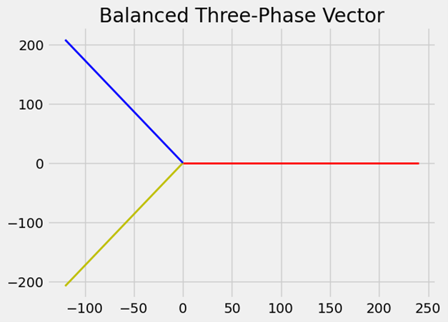
In an ideally balanced power network, the magnitudes of currents and voltages are identical, with phase displacements precisely at 120 degrees. Additionally, this balanced system exclusively consists of a Positive-Sequence Component, without any Negative- or Zero-Sequence Components.
The figure below demonstrates the positive-sequence voltage component within a 240-volt electrical network, representing an ideally balanced system. Such balance is crucial for delivering optimal electricity supply to domestic consumers in South Africa. The single vector depicted corresponds precisely to this positive-sequence component, highlighting the harmony and stability of the electrical network.
True Stories of Network Imbalances
I have learned that an Eskom representative was informed about potential imbalances in network conditions at the Modderbee municipal substation, but this information was possibly dismissed. I am frustrated by the lack of response to my emails seeking collaboration on examining the issue of unbalanced currents and voltages. Despite successful delivery, my first email remained unanswered, and the second was inexplicably erased without being read. The lack of acknowledgment from the recipient is perplexing, especially considering the urgency of the matter. As a result, I am calling out Eskom, City Power, and NERSA in this article to highlight these issues.
City Power Area—Linden
Despite numerous appeals to City Power to investigate potential imbalances in the network at the Roosevelt Park substation in Johannesburg, and even volunteering my services to help pinpoint if this issue was localized, I took the initiative to set up my own Power Quality Monitor at a nearby three-phase installation. I had suspicions that our area was experiencing unbalanced network conditions, and I was keen to confirm this.
City Power Recordings
On the 12th of April 2024, I set up my Power Quality Monitor at a residence in my neighborhood for a duration of roughly 20 hours.
Upon retrieving the device and briefly examining the data, I observed a significant dip in two out of the three phases at 04:23:55. Initially, I was unsure why only two phases were impacted while the third remained stable. However, a meticulous review of the data revealed that our residential area is indeed prone to unbalanced network conditions.
Despite my efforts to have City Power conduct a parallel assessment for unbalanced network conditions, I have yet to receive the requested results. However, I have already provided them with my data.
Data Analyses
As previously mentioned, in an ideally balanced system, the voltage magnitudes should be identical, and the phase shifts should be precisely 120 degrees. Furthermore, such a balanced system should exclusively exhibit a Positive-Sequence Component, with the absence of any Negative- or Zero-Sequence Components.
Therefore, the single vector for this region should mirror the one illustrated in the following image.

Observe that the three phases have the same length and are separated by an exact displacement of 120 degrees. Pay attention to the position of phase 1, depicted by a red line. It lies on the X-axis and is situated to the right of the Y-axis.
The direction of the phase rotation, whether it is clockwise or anti-clockwise, is irrelevant. The line will consistently be located on the X-axis and to the right side of the Y-axis.
Positive-Sequence Component
The positive-sequence component depicted in the Figure 9 below is derived from the recording taken at 21:20:00 on April 12, 2024.
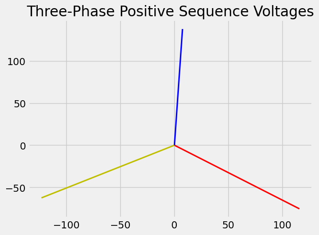
Observe the location of phase 1, indicated by the red line. The whole positive-sequence component has moved in a clockwise direction. Additionally, pay attention to the length of the lines. They are expected to match the length. This evident discrepancy signals an issue.
Don’t wait for the next failure. Click below to download your personal copy of “Navigating Power Imbalances” and gain the expertise you need today.
Positive Sequence Animation
Negative-Sequence Component
The following image illustrates the negative-sequence voltage component as recorded at 21:20:00 on April 12, 2024.
Recall the previous discussion: in an ideally balanced system, a Negative-Sequence Component should not exist. Therefore, the canvas area of Figure 10 should appear empty.
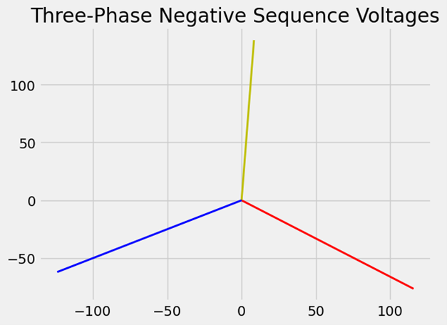
I would like to emphasize that Phase 1, represented by the red line, shares the same angle and magnitude as the red line in the above image, symbolizing the positive-sequence voltage component.
Negative Sequence Animation
Zero-Sequence Component
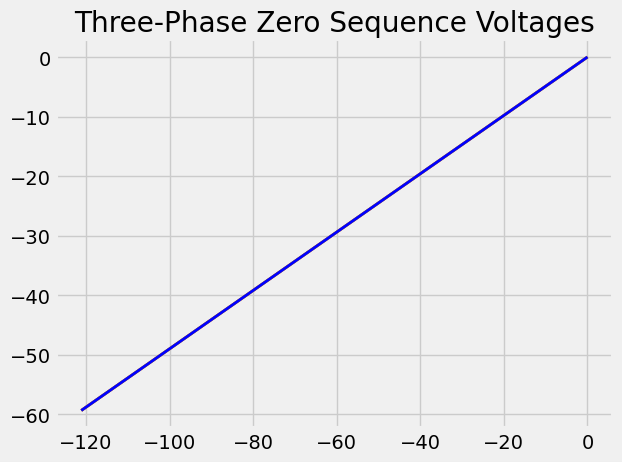
The image below showcases the zero-sequence voltage components as recorded at 21:20:00 on April 12, 2024.
Zero Sequence Animation
Recall the previous statement: a perfectly balanced system should not contain a Zero-Sequence Component. Therefore, the canvas area of the subsequent image should have been empty.
The blue line is the only visible one because the red and yellow lines are concealed beneath it. All three lines share the same magnitude and angle.
Observe the elevated magnitudes of the three zero-sequence components. These should be non-existent, implying there should be no lines whatsoever, or as previously mentioned, it should be presented as an empty canvas.
Linden Cartesian Coordinate System Analysis
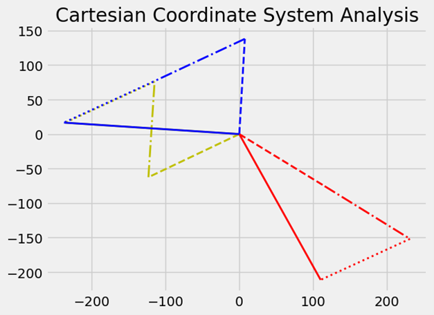
The illustration below showcases the three symmetrical components that make up the voltages, as recorded in Linden at 21:20:00 on April 12, 2024.
A crucial observation is the apparent absence of a solid yellow line.
Before you assume a phase is absent, I can confirm that this is not the case. The phase-displacement between two of the phase-to-neutral voltages is nearly identical. What has occurred is that phases 2 and 3 are almost equal in magnitude and share a similar phase-displacement angle.
Phase-To-Phase Voltages
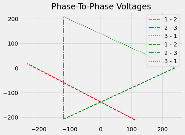
The diagram below presents a comparison between the phase-to-phase voltages of an ideally balanced network and the unbalanced phase-to-phase voltages of a network. These measurements were recorded in Linden at 21:20:00 on April 12, 2024.
The red “triangle” in the diagram symbolizes the measured phase-to-phase voltages, whereas the green dashed-line triangle signifies an ideally balanced network. However, in this instance, the red “triangle” is absent. Instead, the phase-to-phase voltages seem to be depicted as a “straight line”, deviating from the expected triangular representation. This anomaly is due to the phase-to-phase voltage between phase 2 and 3 being only 0.33 volts.
In the Consequences of Unbalanced Voltage in Electrical Systems, several aspects related to three-phase motors are explored. When the voltages in the three phases are not balanced or symmetrical, an off-center ellipse forms. This occurrence signifies that the system is experiencing unbalanced voltages. Specifically, electric motors connected to such an unbalanced network face challenge.
The off-center ellipse results in uneven magnetic forces within the motor windings. Consequently, the motor bearings experience varying stress due to the magnetic field fluctuations. These uneven magnetic forces lead to motor vibration, significantly impacting both performance and longevity.
Motors operating with unbalanced voltages may run inefficiently or even overheat. The torque produced by the motor becomes irregular, causing mechanical stress and potential failure. Now consider the stresses caused by unbalanced voltage supply on a three-phase, 4-pole electric motor supplied by a 50Hz frequency, which then rotates at 1800 rpm.
Conclusion
Primarily, it is crucial to understand that the zero-sequence component is responsible for generating heat in transformers and cables, hence the need for its elimination. Secondly, imbalanced network conditions lead to an extremely high neutral current and elevated circulating currents in the delta windings of transformers. These conditions can cause transformers and cables to overheat, potentially leading to unexpected shutdowns or even more serious failures like cables being burnt off or transformer insulation ignition.
Reflect on the recent surge in reported cable and transformer malfunctions, and then form your own opinion: Are Eskom and other power distributors cognizant of the imbalanced network conditions? Furthermore, do they take adequate measures to inspect the networks for this issue? Based on my observations, it seems unlikely. They appear to disregard any notifications concerning imbalanced network conditions.
A recurring query is: who reaps the benefits from the additional charges customers pay due to unbalanced network conditions? Let us delve into this. Customers require a certain amount of electrical power, or real power, to carry out specific tasks. However, these unbalanced network conditions lead to a substantial rise in inefficient powers, causing an increase in apparent power. Since customers’ bills are primarily based on this apparent power, they end up paying more for these inefficient powers. On the generation side, power must be produced to offset the losses. Each unit generated includes a profit margin. Therefore, the more units produced, the greater the profits. It is important to note that none of the power plants, whether coal-fired, nuclear, or renewable, operate as non-profit entities.
It might be beneficial for individuals like the Eskom executive to peruse this article, along with other articles I have shared on my blog. Additionally, web pages such as Symmetrical Component Analysis and Negative Phase Sequencing could provide further understanding of this concept.
Those who have comprehended the aforementioned information can independently determine the validity of the claim that Modderbee and Linden are not experiencing unbalanced network conditions.
What is crucial is that consumers need to determine if they are willing to pay a significantly higher price for electricity, considering that the issues should be resolved by the power supply distributors, including Eskom.
Equally significant is the fact that imbalances in networks are not readily apparent in power supplies. For instance, in Linden, individuals might assume the power supply is functioning normally by checking the phase-to-neutral voltages. Similarly, in Modderbee, Eskom and electricity department officials might perceive the network as problem-free when they observe that the phase-to-phase voltages are consistent.
If you are under the impression that residing in a different part of the globe shields you from unbalanced network conditions, it might be worth verifying that assumption. As outlined in this document, you might be totally unaware of such occurrences.
Enhance Your Energy Efficiency with Our Expert Power Quality Consultingand
Unlock the Secrets to Stable Electrical Operations
