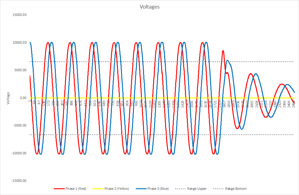
In a balanced three-phase network, the magnitudes of the voltages and currents in all three phases are the same and these voltages and currents phase are shifted symmetrically by 120 degrees to each other. If the magnitudes are not the same and phase-shifts are different from the 120 degrees, the network is unbalanced.
Eskom strive to supply a balanced set of voltages at the supply points. Although Eskom may attempt to supply a balanced set of voltages, they do not. This is probably true for the point of supply at the generator terminals, but between the generator terminals and the end user are Transmission, Distribution and often Reticulation Networks that are not maintained or monitored with the same diligence that is required to supply balanced voltages. Often the network operators are oblivious to unbalances occurring on the network. Perhaps there are Negative Protection System installed on the Transmission Networks, but it is doubtful that such protective devices exist on Distribution and Reticulation Networks.
Low Voltage (LV) network unbalances are caused by unequal phase impedances, single-phase laterals and other structural asymmetries of LV networks, uneven allocation of single-phase consumers across the three phases on mostly rural reticulation networks, unbalanced three-phase loads and random variation of consumption over time. In addition, the presence of single- phase distributed generation, for example single-phase solar inverters also contributes to the phase imbalances occurring in LV networks. However, load asymmetry represents the main cause of voltage and current imbalances in LV networks. Asymmetric faults are another source of voltage or current imbalances, but these are usually transient events and are usually cleared quickly from the grid, so it could often be ignored.
In many cases operators and maintenance crews are unaware of the negative consequences that phase imbalances can have on LV networks and electrical equipment. Current imbalances would lead to a reduction in the serviceable loading capacity of LV cables and distribution transformers. Because of the imbalances, some of the phases could carry higher loads while the remaining phase of phases could be lightly loaded but, the limiting factor for the addition of three-phase loads is the current on the highest loaded phase or phases.
Current imbalances can also cause additional heat losses in distribution transformers and LV cables in both the phase and neutral conductors. These types of losses represent a significant part of the total losses occurring in LV networks.
When end users, such as municipalities, are supplied by unbalanced voltages, induction machines and power converters face adverse effects such as reduced efficiency, increased losses, potentially dangerous overheating and, in some situations, premature failures. At severe voltage or current imbalance levels, some types of protection relays could malfunction, leading to miscoordination, nuisance tripping and lack of selectivity.
In the United States, voltage magnitude variations are limited to ±5% and in most European countries it is limited to ±10%. For the rest of the world, these limits are not much different.
The question is: is Eskom aware what is happening on the Distribution and Reticulation Networks? It is highly unlikely that they do. In a recent unrelated “survey”, I came across a 10-minute averaged voltage unbalance of 327% between Phase 2 and Phase 1.
The second question is: would this be restricted to just the one substation? It is highly unlikely. In another post I will talk about and incident where the Negative Phase Sequence occurred on the Transmission Network which affected the entire region.
In a balanced three-phase network, the magnitudes of the voltages and currents in all three phases are the same and these voltages and the phases voltages and currents are shifted symmetrically by 120 degrees to each other. If the magnitudes are not the same and phase-shifts are different from the 120 degrees, the network is unbalanced.
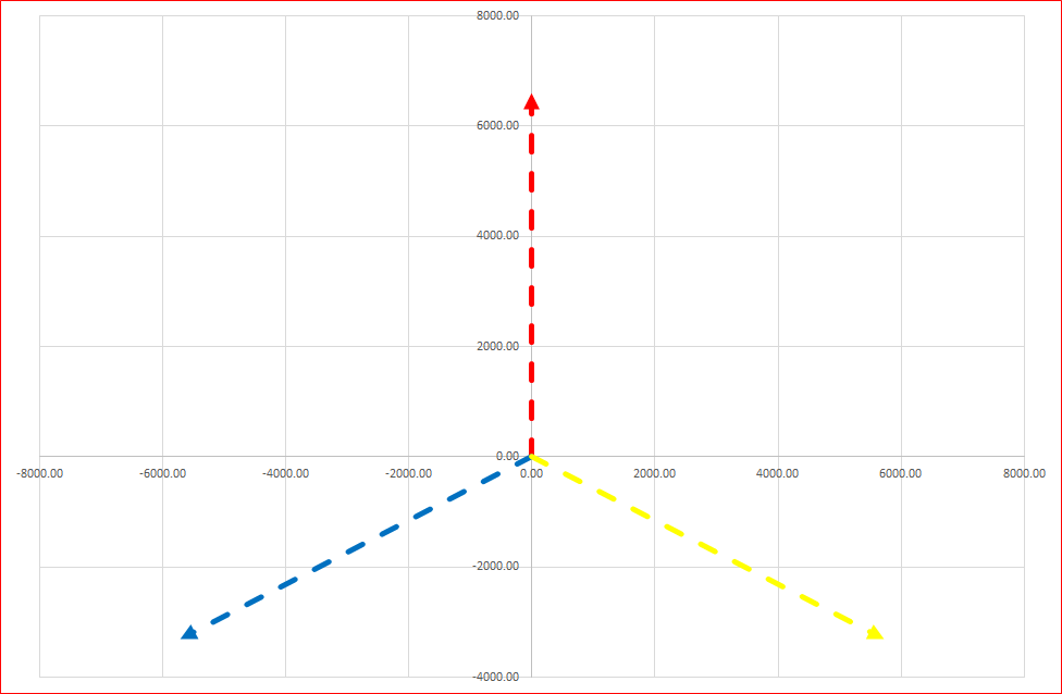
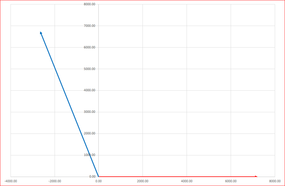
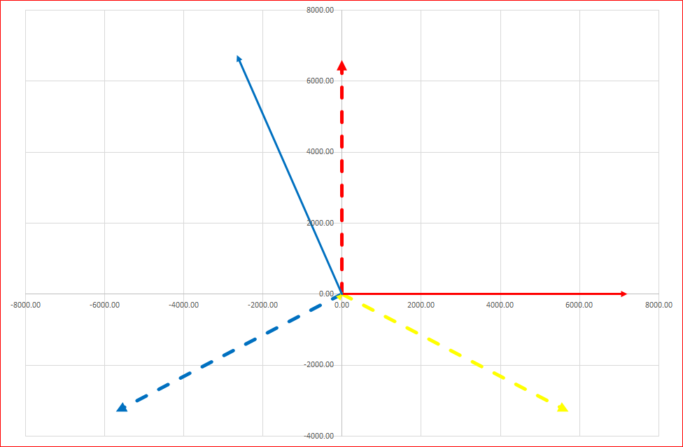
In the picture below, the Voltage Vector for the ideal network is shown with the magnitudes of the voltages being equal and the phases shifted symmetrically by 120 degrees to each other, while the solid lines showing the results recorded. The magnitudes of the actual voltages are not equal since the Yellow/White Phase 2 is almost negligible and the phases are not shifted symmetrically.
Eskom strive to supply a balanced set of voltages at the supply points. But they do not always do that. This is probably true for the point of supply at the generator terminals, but between the generator terminals and the end user are Transmission, Distribution and often Reticulation Networks that are not maintained or monitored with the same diligence to supply voltages with the same magnitudes and phase-shifts as mentioned above.
Often the network operators and maintenance crews are oblivious to unbalances occurring on the network. Perhaps there are Negative Protection System installed at the Generating Stations and on the Transmission Networks, but it is doubtful that such protective devices exist on Distribution and Reticulation Networks.
Low Voltage (LV) network unbalances are caused by unequal phase impedances, single-phase faults and other structural asymmetries of LV networks, uneven allocation of single-phase consumers across the three phases on mostly rural reticulation networks, unbalanced three-phase loads and random variations of consumption over time. In addition, the presence of single-phase distributed generation, for example, single-phase solar inverters also contribute to the phase imbalances occurring in LV networks. However, load asymmetry represents the main cause of voltage and current imbalances in LV networks. Asymmetric faults are another source of voltage or current imbalances, but these are usually transient events and are usually cleared quickly from the grid, so it could often be ignored.
In many cases operators and maintenance crews are unaware of the negative consequences that phase imbalances can have on LV networks and electrical equipment. Current imbalances would lead to a reduction in the serviceable loading capacity of LV cables and distribution transformers. Because of the imbalances, some of the phases could carry higher loads while the remaining phase of phases could be lightly loaded but, the limiting factor for the adding more three-phase loads is the current on the highest loaded phase or phases.
Current imbalances can also cause additional heat losses in distribution transformers and LV cables in both the phase and neutral conductors. These types of losses represent a significant part of the total losses occurring in LV networks.
When end users, such as municipalities, are supplied by unbalanced voltages, induction machines and power converters face adverse effects such as reduced efficiency, increased losses, potentially dangerous overheating and, in some situations, premature failures. At severe voltage or current imbalance levels, some types of protection relays could malfunction, leading to lack of coordination, nuisance tripping and lack of selectivity.
In the United States, the voltage magnitude variations are limited to ±5% and in most European countries it is limited to ±10%. For the rest of the world, these limits for voltage magnitude variations are quite similar.
The question is: is Eskom aware what is happening on the Transmission, Distribution and Reticulation Networks? It is highly unlikely that they do. When looking at Eskom’s Quality of Supply document, there is a lot being said about the consequences of unbalanced voltages, but I cannot find the voltage magnitude variations limits.
In a recent unrelated “survey”, I came across a voltage magnitude variation unbalance of 327% between Phase 2 and Phase 1. The instrument was set to record the values at 10-minute intervals and the 327% is the average over that period. See the picture below.
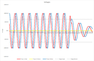
Since the medium-voltage supply comes directly from an Eskom substation which is probably about 20-metres away, one wonders what is going on at the Eskom substation since it is highly unlikely that the voltage unbalance is as a result faulty equipment at the municipal substation. It is as if one phase is completely missing. The same “missing” phase also show an abnormal high current. The neutral current which is supposed to be at or close to zero is also very high.
The second question is: would this be restricted to just the one substation? It is highly unlikely. In another post that is due to come out soon, I will talk about and incident where the Negative Phase Sequence occurred on the Transmission Network which affected the entire region.
Read more about the service we offer.
Newsletter
Join the mailing list and receive our latest newsletters by simply filling in your email address below and then click Subscribe.