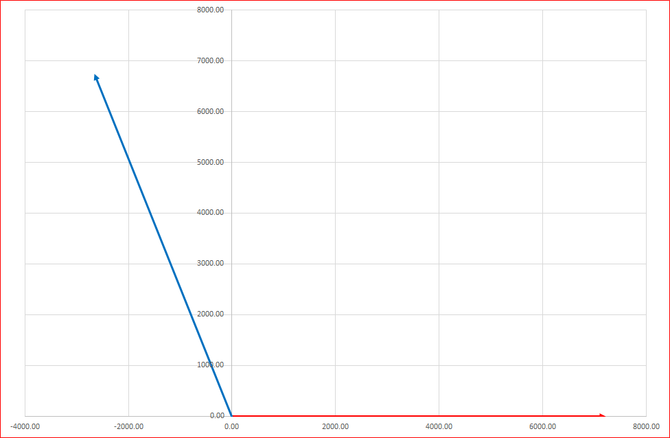
Any repetitive signal, such as three-phase Alternating Current (AC) Voltages and Currents, can be represented as the rotation of a vector around a point. In a balanced three-phase network, the magnitudes of the voltages and currents in all three phases are the same and these phases voltages and currents are shifted symmetrically by 120 degrees to each other. Under this condition, the vector is fixed, and the rate of rotation is constant, and the end of the vector lines will continuously trace a circle. Each pass around the circle represents one complete cycle of the signal.
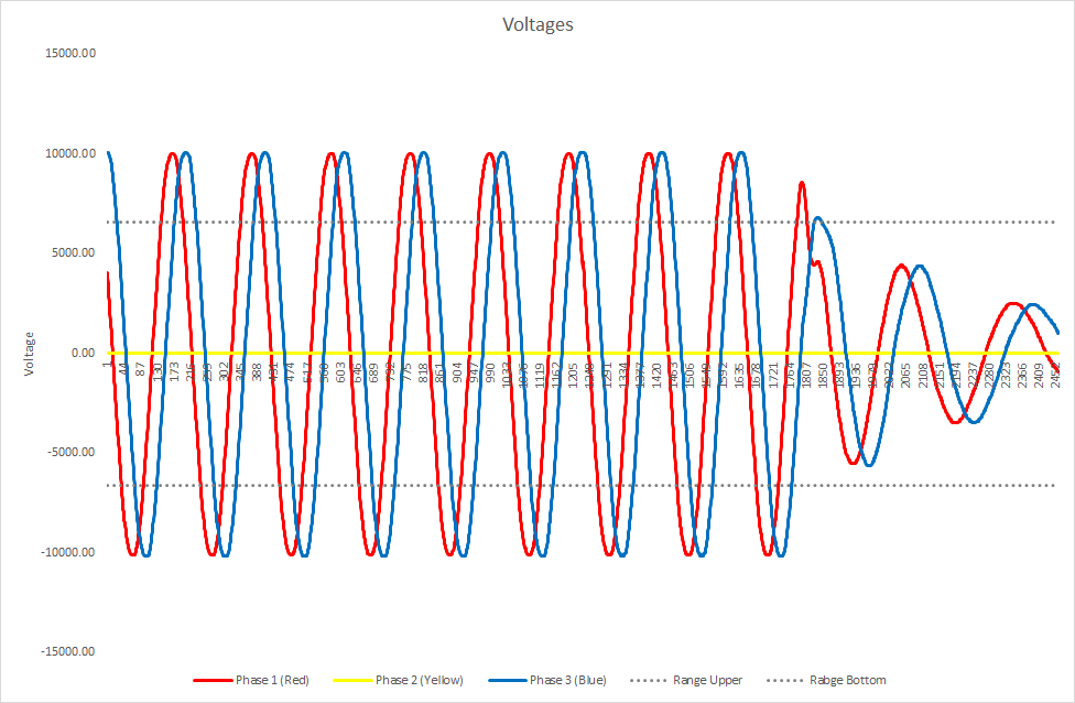
In the video below, the three-phase waves are displayed with the phase-displacement 120-degrees, but Phase 2 (yellow) voltage is reduced by 6%, which may result in 3rd harmonics disturbance represented by the thinner solid line (5% 3rd harmonic) and dotted line representing a 2% 5th Hamonic.
The harmonic disturbances will cause the fundamental sine wave to be distorted. So, the display is not as accurate as it would be displayed on an oscilloscope.
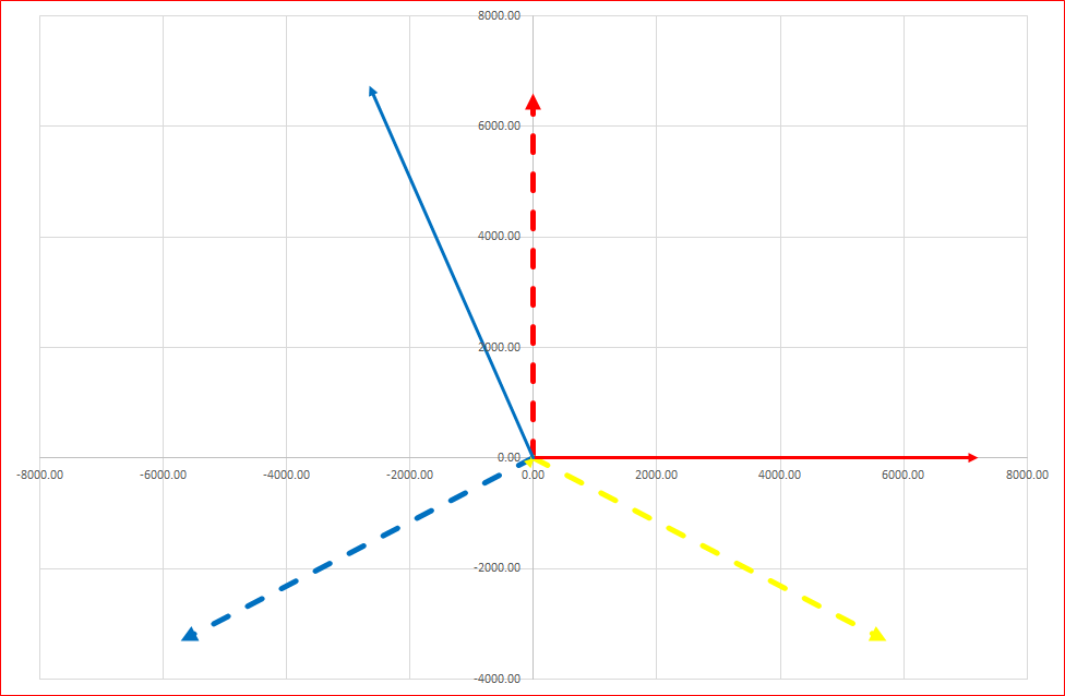
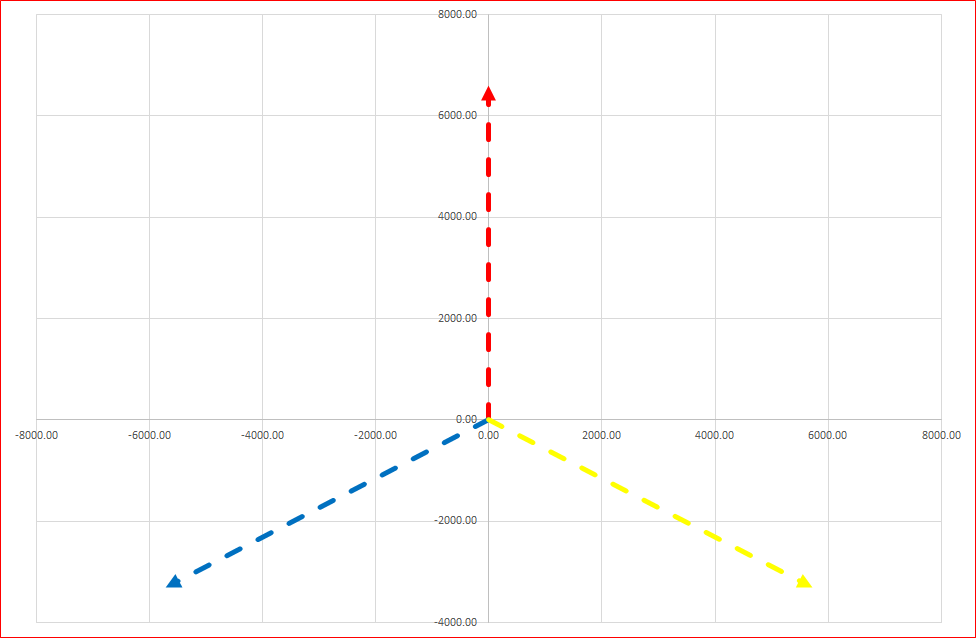
The three-phases are represented as Phases 1 to 3. In this video, the three-phase vector are not colored as per the IEC standards for the UK & EU and several other countries: Phase 1 = should be Brown but displayed as Red, Phase 2 = should be Black but displayed as Yellow and Phase 3 = should be Grey but displayed as Blue. These are the former colors and still widely used by many countries.
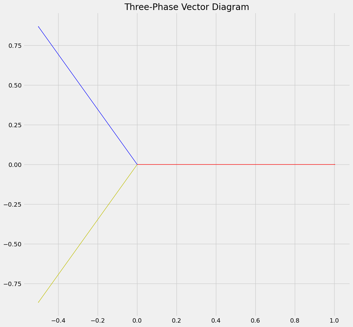
In the vector diagram above, Phase 1 lies along the X-axis with Phase 2 displaced by 120-degrees in a clockwise direction and similarly, Phase 3 is displaced by 120-degrees from Phase 2, also in a clockwise direction. Since the phases would follow a pattern of Phase 1, the Phase 2 and lastly, Phase 3, the normal vector rotation, or more precisely referred to as positive phase sequence, is counterclockwise.
In the vector diagram above, Phase 1 lies along the X-axis with Phase 2 displaced by 120-degrees in a clockwise direction and similarly, Phase 3 is displaced by 120-degrees from Phase 2, also in a clockwise direction. Since the phases would follow a pattern of Phase 1, the Phase 2 and lastly, Phase 3, the normal vector rotation, or more precisely referred to as positive phase sequence, is counterclockwise.
If the magnitudes of the three phases becomes unbalanced or if phases are shifted by something different from the 120 degrees, a negative phase sequence vector is generated. This vector rotates in the opposite direction, which is clockwise.
Because of such voltage unbalances, a common phenomenon found in three-phase power systems which are not well known, additional power losses are being generated. These current and voltage unbalances could damage equipment connected to power system. Again, not always that apparent. In many cases, it happens almost undetected.
Obviously, the greater the unbalances, the greater the risk of damage and more severe it becomes. Another seemingly unknown factor is the substantial financial losses to both distribution network operators and end-customers. This applies to any plant with rotating apparatus and many other user-connected devices. This issue is one of the unrecognisable critical power quality problems which should become a major focal point for utilities and Distribution Generation (DG) industries. But since it is not clearly noticeable, almost no attention is paid to it.
The asymmetry described above, typically appears in the network because of the connection of single-phase customers, which creates uneven load among the phases. This problem, the asymmetry, is further exasperated by large enough single-phase generating devices that are connected to the existing distribution networks. As the non-dispatchable renewable energy systems are being connected to the power systems, the phenomenon of asymmetry will increase to a point where it becomes a major issue, if it is not already the case. Microgrids and charging stations for Electric Vehicles (EVs) are being connected without proper planning or replanning. This has become one of the greatest technical and operation challenges, but hardly any attention is paid to it. Whether that be the so-called third- or first-world countries. Even the best run utilities are not aware of this problem or do not pay enough attention to the phenomenon asymmetry.
It is thus critically important that these issues are mitigated by comprehensive analysis and careful planning. This requires an all-embracing understanding of unbalance propagation and the identification of critical factors that affect such asymmetries.
In a future blog, I will elaborate on the phenomenon of asymmetry and its relation to harmonics.
For further reading, kindly click here.
Newsletter
Join the mailing list and receive our latest newsletters by simply filling in your email address below and then click Subscribe.