Notice: JavaScript is required for this content.
NERSA’s role in South Africa’s electricity sector is pivotal, yet increasingly contested. As the regulator, it must balance utility sustainability with consumer protection, but inefficiencies, opaque processes, and inconsistent decision-making have eroded trust. A critical examination reveals the urgent need for reform—strengthening transparency, aligning with global best practices, and ensuring that regulation drives stability, efficiency, and fairness across the energy landscape.
Best Practices, Power Quality Consulting, Power Quality Matters, Power Quality Monitoring
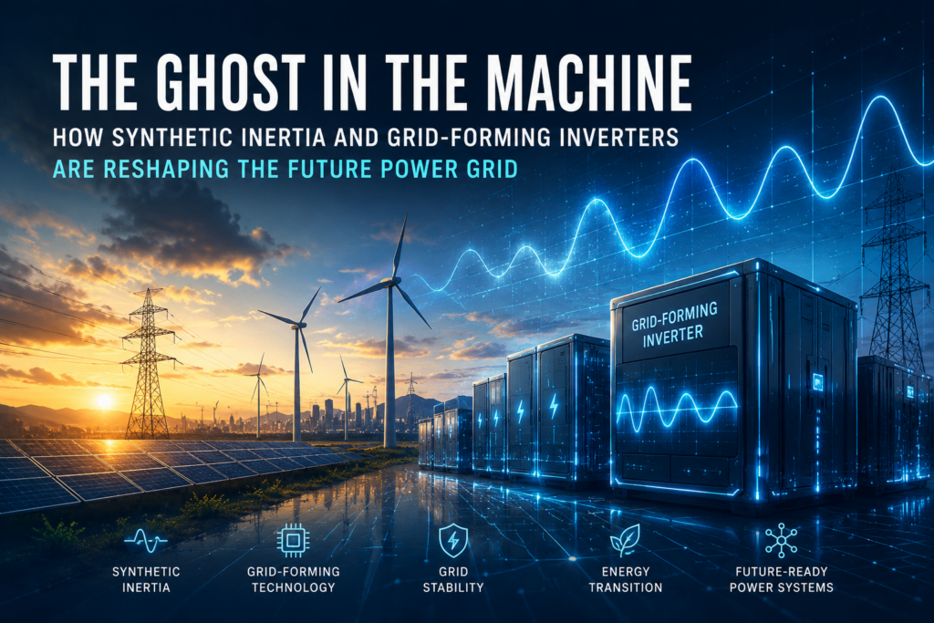
The Ghost in the Machine
18
Jun
Jun
Notice: JavaScript is required for this content.
Best Practices, Power Quality Consulting, Power Quality Matters, Power Quality Monitoring
The R100-Million Battery Blunder

18
Jun
Jun
Notice: JavaScript is required for this content.
Best Practices, Power Quality Consulting, Power Quality Matters, Power Quality Monitoring
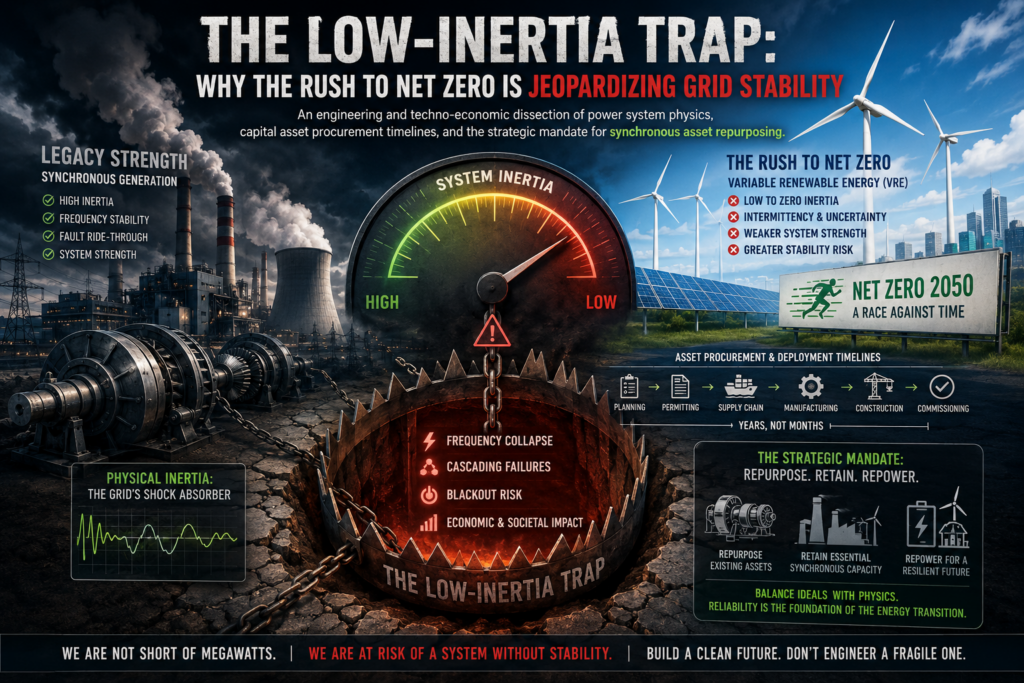
The Low-Inertia Trap
17
Jun
Jun
Notice: JavaScript is required for this content.
Best Practices, Consulting Services, Power Quality Consulting, Power Quality Monitoring
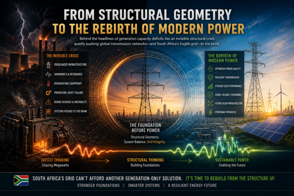
Rebirth of Modern Power
16
Jun
Jun
As South Africa’s electrical grid shifts away from centralized, coal-fired thermal generation toward non-synchronous renewable energy sources, it faces an immediate, existential structural vulnerability: the systemic depletion of power system inertia.
The decommissioning of massive, synchronized spinning generator rotors removes the physical, electromechanical buffer that has historically stabilized the transmission network. While utility-scale Battery Energy Storage Systems (BESS) are critical components of a modern grid mitigation strategy, relying on them as a drop-in replacement for physical inertia introduces a catastrophic protection gap. This briefing addresses the structural mechanics of a Rate of Change of Frequency (RoCoF) Surge and details why digital response times cannot outrun the immediate physics of an inertia-starved power system.
11
Jun
Jun
Notice: JavaScript is required for this content.
Best Practices, Consulting Services, Power Quality Consulting, Power Quality Matters, Power Quality Monitoring
The Anatomy of a Grid Emergency
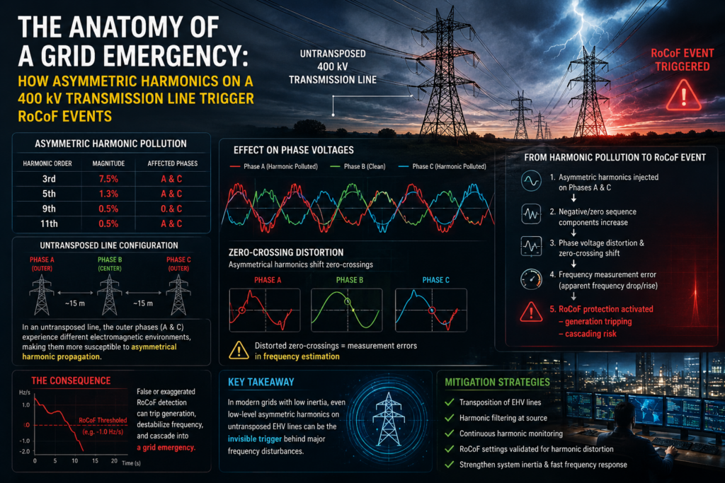
10
Jun
Jun
Notice: JavaScript is required for this content.

08
Jun
Jun
Notice: JavaScript is required for this content.