Power Quality Matters
Phase Imbalance in Distribution Networks
Phase Imbalance in Distribution Networks
Understanding the mechanics, risks, and economic impacts of voltage and current unbalance on electrical power systems.
In an ideal three-phase AC distribution network, the magnitudes of the voltages and currents across all three phases are perfectly equal, and their phase angles are symmetrically displaced by 120 degrees relative to one another.
Balanced System Dynamics
Symmetrical 120° phase displacements allow vector currents to cancel out in the neutral conductor, ensuring high system efficiency and optimal equipment operation.
Unbalanced System Realities
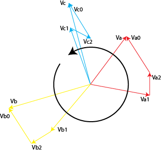
Unequal phase magnitudes or altered phase shifts inject Negative Phase Sequence (NPS) components, leading to localized heating, losses, and motor torque suppression.

Primary Causes of Network Imbalance
Phase unbalance is primarily introduced by asymmetrical load distribution and physical transmission constraints across the utility grid, including:
-
Unequal Single-Phase Load Allocation: Heavy concentration of residential or commercial single-phase loads connected unequally across individual phases.
-
Untransposed Transmission Lines: Asymmetrical physical spacing between conductors, causing impedance differences ($Delta Z$) across phases.
-
Unbalanced Distributed Generation: Single-phase PV solar installations feeding power back unevenly into localized distribution transformers.
Systemic Consequences & Operational Hazards
Utilities and industrial facility operators face severe operational and financial risks when phase unbalance exceeds international standards (such as NRS 048 or IEEE 1159 limits of 1%–2%):
1. Rotating Machinery Overheating
Negative sequence currents create a reverse-rotating magnetic field within induction motors. This acts as a counter-torque, producing severe rotor heating, insulation degradation, and requiring motor derating.
2. Increased Neutral Line Losses
When phase currents no longer sum to zero, significant current flows through the neutral conductor. This results in unnecessary $I^2R$ power losses and excessive ground-potential rise.
Mitigation Strategies
Correcting phase unbalance requires a combination of continuous power quality logging, strategic load balancing, and active compensation technologies:
- Dynamic Load Redistribution: Re-allocating single-phase feeders across distribution boards to equalize phase demand.
- Static VAR Compensators (SVC) & STATCOMs: Implementing fast-acting electronic devices capable of providing phase-by-phase reactive power compensation.
- Transmission Transposition: Physically transposing long-distance high-voltage lines to balance mutual line impedances.
Need to Assess Your Network’s Phase Stability?
Agulhas Utilities Corporation provides comprehensive diagnostic audits, Class-A power quality logging, and full mitigation engineering for utility and industrial clients.
Request a Diagnostic Audit